Both series and parallel wiring can power multiple devices using current flow through the wires. But which is better for the outlet wiring is quite a subject of discussion.
Most of the 120 V outlets should be wired in parallel circuits. That allows every circuit to have its independent hot and neutral wires to maintain a continuous circuit pathway without interrupting each other. In such a case, even if one outlet is not working, the other outlets won’t be affected.
While wiring is best depends on the usage method. This guide will explain everything about series and parallel wiring, the difference, the benefits, and which suits the present situation.
Check out our list of top-handpicked products for all your electrical, appliance, and HVAC system needs to keep your home running smoothly.
This post includes some affiliate links.What is a Series circuit?
A series circuit is a closed circuit where the electrical current flows in one direction.
The current in the series elements is the same as the source current.
The devices connected to the circuit loop are connected in a continuous row.
If any device fails, the whole circuit will disrupt, and all the devices will stop working.
The circuit’s energy lessens by adding a new outlet or component.

Should you wire outlets in series?
As I said, wiring outlets in series means there will be only one pathway for the current flow.
If one device or light goes off, all other devices connected to the circuit will turn off.
So, should you prefer a series circuit?
Generally, there is no problem in wiring an outlet in series.
Series circuits are mostly used in simple circuits where multiple failure chances are less.
It will control multiple devices with a single switch, for example, industrial environments, landscape luminaries, Christmas tree lights, and street lamps.
Lawnmowers are also wired in series for safety purposes. They have only two buttons or switches to turn on.
Why should you wire outlets in series? – Advantages
Let’s look at the advantages of wiring the outlets in series:
- The series circuits do not overheat easily. So, they can easily be around flammable sources.
- The series circuits are easy to learn, design, and repair.
- Since there is only one pathway, all the components will have a constant current.
Why should you not wire outlets in series? – Disadvantages
Despite having such good merits, the series wiring will have some demerits which do not make them an ideal choice:
- If any one component fails, the entire circuit will break down.
- If you increase the number of components, there will be a rise in the resistance. And as we all know, higher resistance leads to overheating and fire hazards.
That is why you should not wire the outlets with a series circuit, especially in houses.
What is a Parallel circuit?
Outlets wired parallelly allow the current to flow across two or more pathways.
All the outlets connected to the parallel circuit will have the same voltage.
The voltage across all the parallel outlets is the same as the source voltage.
The current in each element will change based on the impedance or resistance of each element.
The devices tapped in this circuit loop are connected in a column form.
If any one device fails, the remaining circuit will keep working.
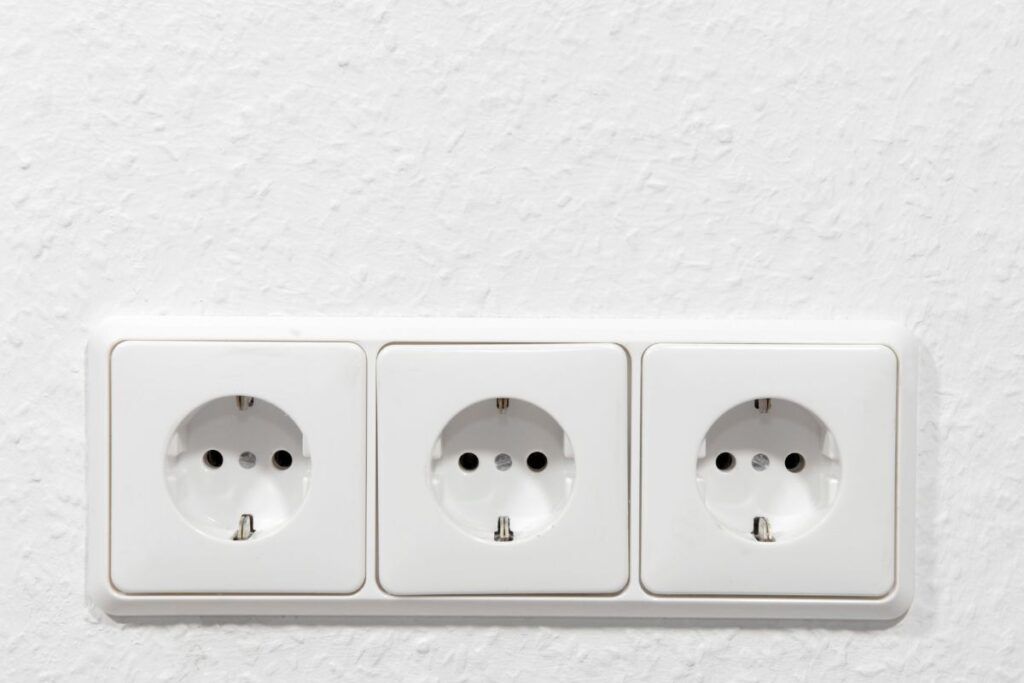
A parallel circuit is used in most normal houses for outlets, switches, fans, light fixtures, and other common 120V circuits.

Should you wire outlets in parallel?
Parallel wiring is good for both industrial and residential environments.
Nowadays, Christmas lights and street lights are wired in parallel.
When one goes off, the other remains the same.
Except for the switches, almost all the devices in the residential houses should be wired in a parallel circuit.
Since parallel circuits have multiple pathways for the current flow, most people prefer them nowadays.
Why should you wire the outlets in parallel?
Let’s look at some advantages to ensure why people should wire outlets in parallel:
- All components attached to the circuit will consistently share the same current amount.
- Connecting or detaching a component will not affect the other components or the circuit.
- The current can pass through different paths if a component has any fault. The feature is good for circuits with several devices like light circuits.
Why is parallel sometimes not preferred?
Despite having some good advantages, some people still prefer series over parallel. Here are the reasons:
- While wiring an outlet with a parallel circuit, you will require a lot of wires. It can make the connection messy and later cause problems in separating.
- Due to multiple pathways, there is a decreased resistance. As a result, you cannot increase the voltage.
- Finding faults in parallel circuits is more complicated than the series circuit due to being multidirectional.
Due to these reasons, some people recommend not to wire the outlets in parallel, but in series.
Which one should you prefer? Parallel vs Series

You can wire the outlets in both series and parallel.
But, the circumstance and the benefits you receive make you select between the two.
Let’s have a look at some major differences between the two circuit types to gather better knowledge about which one to prefer:
Number of branches
The series wiring has one branch, through which the current passes from one device to another in a linear form.
The parallel circuit splits into different pathways where each device stays independent and does not flow into the next device.
The pathways affect the circuit reaction to the failure of one component and power distribution to each of the devices.
Common use case scenarios
A series circuit means you will see a single branch circuit for numerous devices with only one point of failure.
This type of circuit is used in large-scale industrial settings where you see hundreds of components.
Controlling them with a single-branch circuit is easier and faster.
The settings will become complicated if you use a parallel circuit.
Parallel circuits are better for locations where safety is a concern, for instance, houses.
If one component fails, the others should run.
Current direction and distribution
The electricity direction in the series circuit is unidirectional.
The series circuit has only one single lane, and there is no other way for the current to flow or split.
So, any interruption in the current flow will affect the devices connected to the circuit.
On the contrary, parallel circuits are multidirectional.
Since it has multiple directions, the current will split and flow through other directions.
So, an interruption will not affect the whole circuit during operation.
All the devices will have the same current flow in a series circuit.
But on a parallel circuit, the current is divided among each device.
Voltage distribution
In a series circuit, the voltage distribution occurs among the devices within the circuit.
The first device in the current will receive the maximum voltage, whereas the last device will receive very little current.
If you use a series circuit for your lights, they will provide dim light when you add up more components.
On the contrary, outlets in parallel wiring will provide an equal amount of voltage to all the components.
The exception is that the single parallel lane will have multiple devices, which works as a mini-series circuit within a large parallel circuit.
In such a condition, the voltage will get distributed like the series circuit between the devices on the individual lane.
Home usage and effects on other devices
Since a single failure can disrupt an entire circuit, the series wiring is not recommended for household outlets.
It will be frustrating to see your refrigerator not working just because a light blew up.
Not just the fridge but the entire house will go down if a single device blows off.
Such things are against the electrical code guidelines as it is a safety hazard.
So, houses prefer a parallel circuit where the other devices won’t be affected due to a single device’s failure. If one fails, others should still work.
Power drawing quantity
The power draw will fade whenever you add a device to your series wiring.
The first device consumes more power than the one at the last.
On the contrary, the devices in parallel wiring will draw the same amount of power, be it the first or the last.
Reliability
In a series circuit, the failure of one device will turn down the entire circuit. So, it is not reliable enough.
A series circuit is used for areas where wiring outlets in parallel can be troublesome.
The circuit will keep functioning in parallel wiring even if one device malfunctions. So, its reliability is more.
That is why it is commonly used in houses where the areas should be lit even if one device malfunctions, like rooms or a car.
Electrical code guidelines
Connecting the outlets in series is considered a safety hazard, and thus it violates the electrical code guidelines.
Parallel circuits are considered the safest and most efficient wiring configuration.
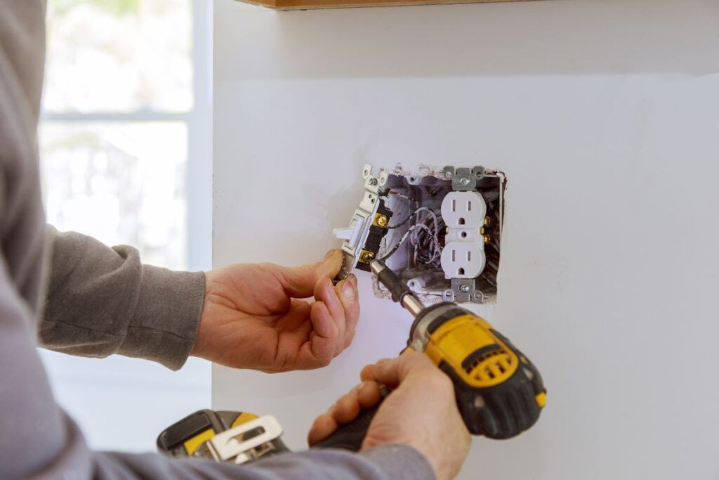
How to wire outlets in series?
Before starting the work, turn off all the power in the circuit breakers and electrical panels.
Check the outlet with a multimeter to confirm the power is off.
Below are the steps to wire outlets in series:
Disconnect wires from the first outlet
Remove the hot, neutral, and ground wires from the first outlet, but keep them inside the box.
Run the wire length from the second outlet going to the first one.
Drill holes into the studs and run the wire through them from one outlet to another. It will be easier in the new construction.
For the older construction, remove the drywall.
Unscrew the small knockout plate on the box’s side, insert an 8-inch wire in each box, and cut the ends with a knife.
Cut the taps to wire the outlets.
Cut the taps, pigtails, and conductors to wire the outlet in series.
The taps are the short length of the wires, and you will cut three of them. It should have one each of hot, neutral, and ground.
Cut only a few inches in length, strip off ½ inch of insulation from the ends, and keep them aside.
Prepare to wire the second outlet.
For preparing the second outlet:
- Cut off 4 inches of the sheath from the wire inside the box.
- Separate the three wires and strip ½ inch of the insulation from each.
- Connect the end of the black wire to the brass terminal and screw the white wire to the silver terminal.
- Now, screw the ground wire to the metal screw inside the junction box.
Wire the screws
Now, wire the series.
- Strip off ½ inch insulation from the wire ends in the first outlet box.
- Bring the black wire to the second box, the black wire into the first outlet, and the black tap together.
- Twist the bare ends of the three wires.
- Secure them with a wire connector and cover them with electrical tape.
- Keep the tap’s other end free.
- Repeat the same thing with the white wires and the ground wires.
- Connect the black tap’s loose end to the brass terminal, the white tap’s end to the silver terminal, and the ground tap to the ground screw inside the box.
You have successfully wired the outlet in series.
Since the steps are complicated, you can hire a professional electrician to wire.
How do you wire outlets in parallel?
In parallel wiring, you must wire the neutral and live wires by pigtail.
Turn off the power before working on any electrical projects. Let’s begin with the steps:
Wire the outlets in the middle of the circuit
Once you turn off the power, you need to wire the outlets in the middle of the circuit. The process will have 4 sub-steps:
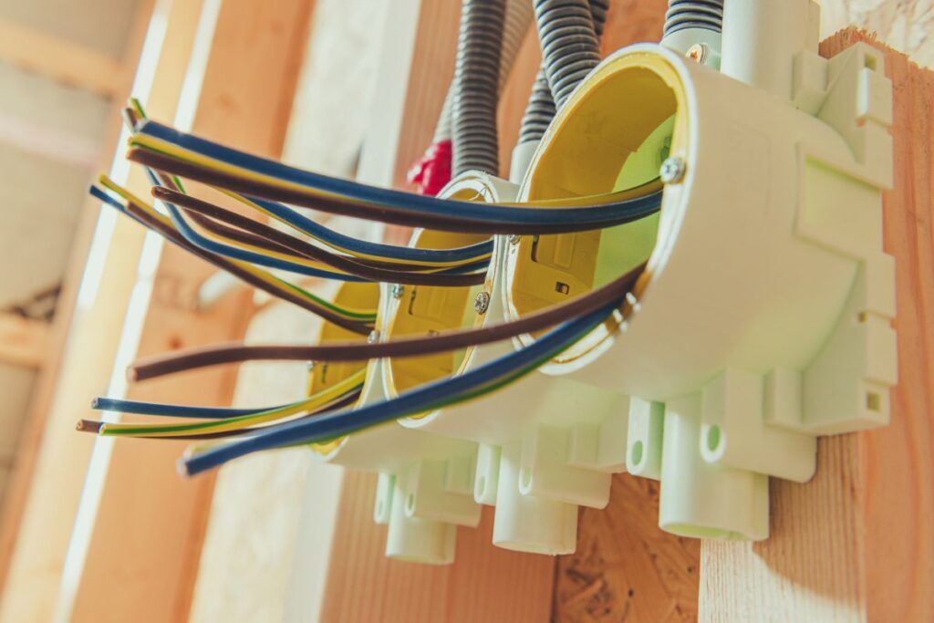
Run up the Romex
The outlets up to the last are considered to be in the middle.
Romex is a non-metallic sheathing for wires.
Run up the Romex through the first outlet box’s underside.
Strip off 6 inches of the insulation to separate the 3 wires – black, white, and green or bare – from inside the Romex.
Strip off the insulation from the wires.
Strip off around 1 inch of the insulation from the black, white, and green wires.
On the outlet, you will find 2 silver screws, 2 brass screws, and 1 green screw.
Attach the white wire to the lower silver screw and the black one to the lower brass screw.
Feed the Romex through the outlet box’s top hole.
Feed enough Romex through the box’s top hole and extend it to the next outlet.
Bring it from the hole in the second outlet box’s bottom.
Leave around 6 inches extending to the first outlet box and the second box, respectively.
Go back to the first outlet and strip the wires similarly.
Twist the wires together.
Connect the second white wire to the upper silver screw and the second black wire to the upper brass screw.
Connect the small green wire with the green screw in the first outlet.
Now, pigtail the other end with the 2 ground wires coming and leading out of the first outlet box.
Twist the 3 wires together and screw a wire nut at the end for the pigtail.
Connect the other outlets.
Connect every outlet in the middle in the same way.
Lead into every outlet box from the bottom and exit through the top to move to the next outlet.
Pigtail the ground wires in all the outlet boxes.
Attach a small green wire from each pigtail with the green screw of the outlet.
Use an extra wire length to make the ground connections if needed.
Complete the circuit end
Now, it is time to complete the circuit.
Here, enter only the Romex in the outlet box.
Strip the Romex in the box and the individual hot and neutral wires.
Connect the white wire to the upper silver screw and the black one to the brass.
Pigtail with the ground wire from the Romex and the ground wire length connecting to the green screw. You are done.
Check each connection once again. Make sure to avoid attaching the outlets to the wall right now.
Turn the power to check and test the powers.
Once you have confirmed every connection’s performance, install them in the outlet boxes.
Screw the faceplates back.
Since the steps are too complicated, consider calling a professional for the job.
Final thoughts
You may wire the outlets in both series and parallel. It depends on the circumstances. Wiring outlets in parallel are preferred in the houses. They have multiple paths for the current to flow. When one device in the house fails, the others should keep working.
On the other hand, the series circuit has only one pathway for current flow. If one device fails, the entire circuit disrupts. If you wire your house outlets in series, the whole house’s power will be down if one device fails. It is against the electrical code guidelines.
Even with such a feature, a series circuit is preferred in places with large-scale industrial settings, for example, factories, street lamps, or Christmas lights. It would be challenging to handle hundreds of devices separately in such places. That is why the series circuit is preferred in such areas.
Why are house outlets not wired in series?
The energy used in each device reduces when you wire extra items in series. As a result, 3 devices wired in series will give the outlet insufficient current.
Which is safer: series or parallel?
Both are safe. A series circuit is safe for large-scale industrial settings with hundreds of devices and can turn them off together. Parallel circuits are safe in houses where safety is a concern.
Reference: Electrical Wiring Wikipedia, Home wiring Wikipedia.